中小型企业网络组建实验

使用华为 eNSP 尝试了一次中小型企业网络组建实验

问题 1

公司总共有250人,技术部93人,市场部24人,人事部10人,财务部5人,总经办4人,其他员工114人,现将两个C类地址 192.168.1.0/24 、 192.168.2.0/24用来给以上部门划分不同子网。

分析

  • 给每个部门分别划分一个子网
  • 题目未设定每名员工的设备数量,所以假设为 1 台
  • 每个子网设计上应当留有一定的可用地址,以便后续的网络设备和软件部署
  • 考虑各部门未来发展需要,且题目给出的环境允许,给每个部门预留出当前部门人数 30% 以上的可用地址

解决方案

部门名称 部门人数 子网地址 除去人数后剩余可用地址数量
技术部 93 192.168.1.0/25 33
市场部 24 192.168.1.128/26 38
人事部 10 192.168.1.192/27 20
财务部 5 192.168.1.224/28 9
总经办 4 192.168.1.240/28 10
其他员工 114 192.168.2.0/24 140

上述方案是一个理论上可满足实际需求和未来发展需要的较优解

问题 2

使用任意模拟器组建该网络拓扑结构,并实现以下要求

  1. 部门之间相互隔离
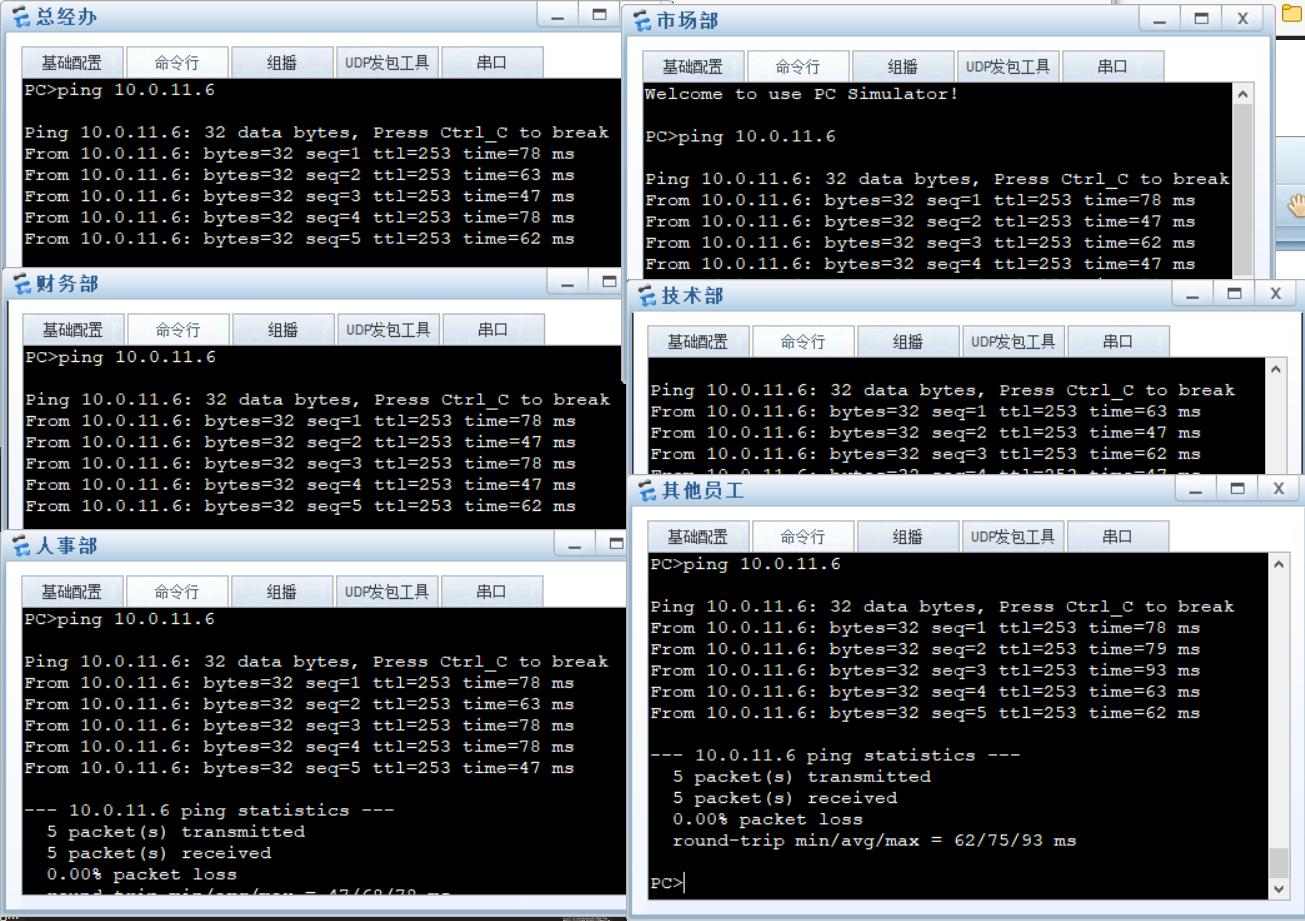
  2. 所有部门能访问OA系统
  3. 开发平台只有技术部能访问
  4. 财务系统只有财务部能访问
  5. 所有人都能访问Internet(外网)
  6. 将门户网站做外网映射

整体分析

  • 题目未对各部门的网络地址做出要求,故沿用问题 1 中的方案作为该题的背景
  • 最近在尝试接触和摸索华为 eNSP,故使用华为 eNSP 来模拟进行实验

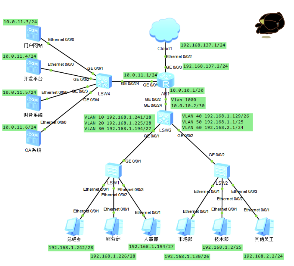
各终端的 IP 地址及网络拓扑结构如下图所示:
需求 1:各部门之间相互隔离

该需求可使用 VLAN 技术实现

各 PC 的 IP 配置如图中所示

在图中的 LSW1 上

1
2
3
4
5
6
7
8
9
10
11
12
13
14
15
16
17
18
19
20
21
22
23
<Huawei>system-view
[Huawei]sysname L2S1

[L2S1]vlan batch 10 20 30

[L2S1]interface Ethernet 0/0/1
[L2S1-Ethernet0/0/1]port link-type access
[L2S1-Ethernet0/0/1]port default vlan 10
[L2S1-Ethernet0/0/1]quit

[L2S1]interface Ethernet 0/0/2
[L2S1-Ethernet0/0/2]port link-type access
[L2S1-Ethernet0/0/2]port default vlan 20
[L2S1-Ethernet0/0/2]quit

[L2S1]interface Ethernet 0/0/3
[L2S1-Ethernet0/0/3]port link-type access
[L2S1-Ethernet0/0/3]port default vlan 30
[L2S1-Ethernet0/0/3]quit

[L2S1]interface GigabitEthernet 0/0/1
[L2S1-GigabitEthernet0/0/1]port link-type trunk 
[L2S1-GigabitEthernet0/0/1]port trunk allow-pass vlan 10 20 30

在图中的 LSW2 上

1
2
3
4
5
6
7
8
9
10
11
12
13
14
15
16
17
18
19
20
21
22
23
<Huawei>system-view
[Huawei]sysname L2S2

[L2S2]vlan batch 40 50 60

[L2S2]interface Ethernet 0/0/1
[L2S2-Ethernet0/0/1]port link-type access
[L2S2-Ethernet0/0/1]port default vlan 40
[L2S2-Ethernet0/0/1]quit

[L2S2]interface Ethernet 0/0/2
[L2S2-Ethernet0/0/2]port link-type access
[L2S2-Ethernet0/0/2]port default vlan 50
[L2S2-Ethernet0/0/2]quit

[L2S2]interface Ethernet 0/0/3
[L2S2-Ethernet0/0/3]port link-type access
[L2S2-Ethernet0/0/3]port default vlan 60
[L2S2-Ethernet0/0/3]quit

[L2S2]interface GigabitEthernet 0/0/2
[L2S2-GigabitEthernet0/0/2]port link-type trunk 
[L2S2-GigabitEthernet0/0/2]port trunk allow-pass vlan 40 50 60

在三层交换机上

1
2
3
4
5
6
7
8
9
10
11
12
13
14
15
16
17
18
19
20
21
22
23
24
25
26
27
28
29
30
31
32
33
34
35
36
37
<Huawei>system-view
[Huawei]sysname L3S
[L3S]vlan batch 10 20 30 40 50 60

[L3S]interface GigabitEthernet 0/0/1
[L3S-GigabitEthernet0/0/1]port link-type trunk
[L3S-GigabitEthernet0/0/1]port trunk allow-pass vlan 10 20 30
[L3S-GigabitEthernet0/0/1]quit

[L3S]interface Vlanif 10
[L3S-Vlanif10]ip address 192.168.1.241 28
[L3S-Vlanif10]quit

[L3S]interface Vlanif 20
[L3S-Vlanif20]ip address 192.168.1.225 28
[L3S-Vlanif20]quit

[L3S]interface Vlanif 30
[L3S-Vlanif30]ip address 192.168.1.193 27
[L3S-Vlanif30]quit

[L3S]interface GigabitEthernet 0/0/2
[L3S-GigabitEthernet0/0/2]port link-type trunk
[L3S-GigabitEthernet0/0/2]port trunk allow-pass vlan 40 50 60
[L3S-GigabitEthernet0/0/2]quit

[L3S]interface Vlanif 40
[L3S-Vlanif40]ip address 192.168.1.129 26
[L3S-Vlanif40]quit

[L3S]interface Vlanif 50
[L3S-Vlanif50]ip address 192.168.1.1 25
[L3S-Vlanif50]quit

[L3S]interface Vlanif 60
[L3S-Vlanif60]ip address 192.168.2.1 24
[L3S-Vlanif60]quit

验证,各部门间不可相互访问

至此,需求 1 已经实现,下面继续完成其余部分的网络配置

需求 2:所有部门能够访问 OA 系统

先打通 AR1 与 LSW3 之间的连接

在三层交换机 LSW3 上

1
2
3
4
5
6
7
8
9
10
[L3S]vlan 1000
[L3S-vlan1000]quit
[L3S]interface Vlanif 1000
[L3S-Vlanif1000]ip address 10.0.10.2 30
[L3S-Vlanif1000]quit
[L3S]interface GigabitEthernet 0/0/24
[L3S-GigabitEthernet0/0/24]port link-type access
[L3S-GigabitEthernet0/0/24]port default vlan 1000
[L3S-GigabitEthernet0/0/24]quit
[L3S]ip route-static 10.0.11.0 24 10.0.10.1

在 AR1 上

1
2
3
4
5
6
7
<Huawei>system-view
[Huawei]sysname R1
[R1]interface GigabitEthernet 0/0/2
[R1-GigabitEthernet0/0/2]ip address 10.0.10.1 30
[R1-GigabitEthernet0/0/2]quit
[R1]ip route-static 192.168.1.0 24 10.0.10.2
[R1]ip route-static 192.168.2.0 24 10.0.10.2

进行测试,当前配置过的网络无误后继续完成其余部分的配置

在 AR1 上

1
2
[R1]interface GigabitEthernet 0/0/1
[R1-GigabitEthernet0/0/1]ip add 10.0.11.1 24

为 OA 系统服务器配置上 IP,测试,可实现需求 2

需求 3:开发平台只有技术部能访问

可使用使用 ACL 实现,在 LSW4 上

1
2
3
4
5
6
7
8
<Huawei>system-view 
[Huawei]sysname DMZSwitch
[DMZSwitch]acl 2001
[DMZSwitch-acl-basic-2001]rule permit source 192.168.1.0 0.0.0.127
[DMZSwitch-acl-basic-2001]rule deny source any
[DMZSwitch-acl-basic-2001]quit
[DMZSwitch]interface GigabitEthernet 0/0/2
[DMZSwitch-GigabitEthernet0/0/2]traffic-filter outbound acl 2001

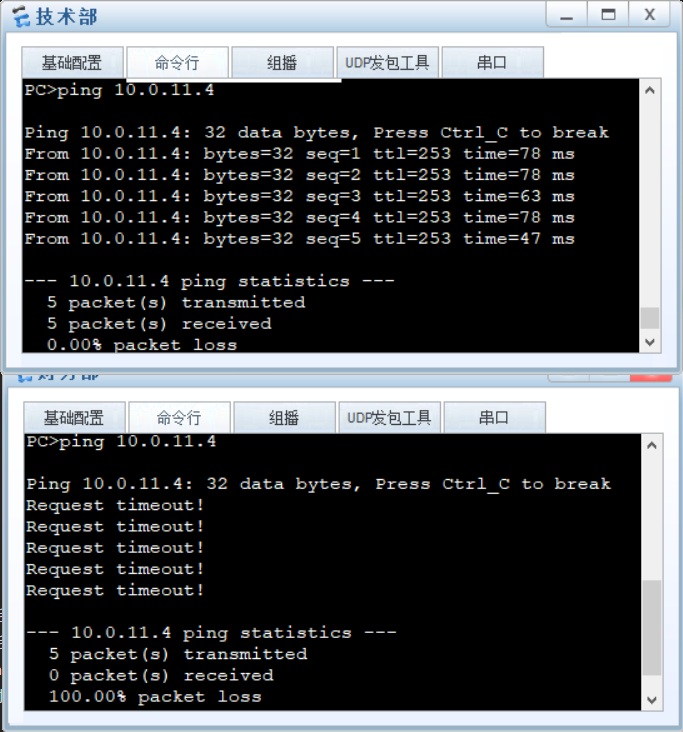
验证,只有技术部能够访问开发平台,其他部门不可访问

需求 4:财务系统只有财务部能访问

需求 3 类似,可以使用 ACL 实现

在 LSW4 上

1
2
3
4
5
6
[DMZSwitch]acl 2002
[DMZSwitch-acl-basic-2002]rule permit source 192.168.1.224 0.0.0.15
[DMZSwitch-acl-basic-2002]rule deny source any
[DMZSwitch-acl-basic-2002]quit
[DMZSwitch]interface GigabitEthernet 0/0/3
[DMZSwitch-GigabitEthernet0/0/3]traffic-filter outbound acl 2002

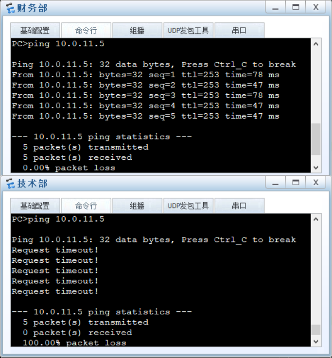
验证,只有财务部能访问财务系统

需求 5:所有人都能访问 Internet(外网)

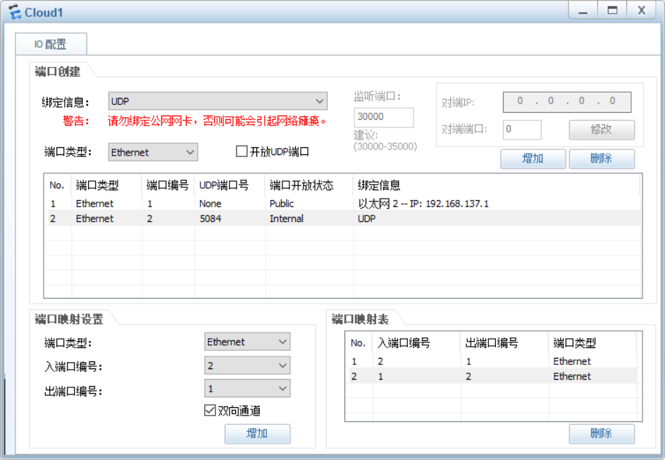
Cloud 1 配置如图所示
在 R1 上

1
2
3
4
[R1]interface GigabitEthernet 0/0/0
[R1-GigabitEthernet0/0/0]ip address 192.168.137.2 255.255.255.0
[R1-GigabitEthernet0/0/0]quit
[R1]ip route-static 0.0.0.0 0.0.0.0 192.168.137.1

在 LSW3 上

1
[L3S]ip route-static 0.0.0.0 0.0.0.0 10.0.10.1

验证,应当所有人都能访问 Internet

此处因 eNSP 的 bug 无法验证

Cloud 1 的配置过程可以参考:详解华为模拟器eNSP添加路由器连接互联网_哔哩哔哩,视频中同样出现了与我实验相同、eNSP 引起的故障,此问题被用户反映普遍存在,没有可靠的解决方案

需求 6:将门户网站做外网映射

1
2
3
[R1]interface GigabitEthernet 0/0/0
[R1-GigabitEthernet0/0/0]nat server protocol tcp global 192.168.137.3 80
 inside 10.0.11.3 80

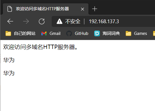
验证,从外网可以访问门户网站

吐槽

华为的 eNSP 真的很难令人满意,糟糕的设备启速度、设备放着不动会莫名其妙掉线还有网络上普遍反应存在的外网桥接问题,令实际使用体验很差